• Welcome to The Audio Annex! If you have any trouble logging in or signing up, please contact 'admin - at - theaudioannex.com'. Enjoy!
  • HTTPS (secure web browser connection) has been enabled - just add "https://" to the start of the URL in your address bar, e.g. "https://theaudioannex.com/forum/"
  • Congratulations! If you're seeing this notice, it means you're connected to the new server. Go ahead and post as usual, enjoy!
  • I've just upgraded the forum software to Xenforo 2.0. Please let me know if you have any problems with it. I'm still working on installing styles... coming soon.

Flint Acoustics: Custom High Fidelity Patio Speakers (future self-powered)

Flint

Prodigal Son
Superstar
Amongst my activities, including looking for work, getting new funding for my startup, designing for another audio startup, and trying pay my bills, I was commissioned to build a nice set of high-fidelity loudspeakers to be mounted on a screened in porch (protected outdoors).

I've been working on these for weeks, and now I will share with this group the process and results.

I started by choosing drivers which I believe will not only sound good, but also survive in the typical weather conditions on a New England house's screened in porch. I don't think they could handle the freezing, wet & dry winters, so the focus was to be hardy in spring, summer and autumn. So, the components need to survive fluctuating humidity levels and temps ranging from about freezing to highs nearing 100 degrees Fahrenheit. While doing my research I stumbled onto some great mid-woofer drivers from Dynavox which had no parts susceptible to rot from humidity (like paper cones or ferrous frames). They also happened to be close-out from the merchant at more than half their regular price. WIN! Once I chose the mid-woofers, I shopped for a reasonably priced tweeter which should match the performance of the woofer, fit the budget, and also be reliable in a semi-outdoor installation. For that, I chose a nice Peerless ring radiator tweeter.

With the woofers and tweeters picked out and delivered, I then worked with the future owner to determine the enclosure shape and look. We settled on a cabinet which is wider than tall, as flat as could be made and still sound good, and which can easily be installed in the spring and removed in the winter. Since they will be mounted high on an outdoor wall, I chose to angle the baffle downward, place the woofer above the tweeter, and tune the enclosure for being close to two reinforcing surfaces (wall and ceiling) without sounding bass heavy, or too "phat" in the bass.

Here are drawings from which I build the enclosures:

Dynavox_Initial_Drawing_Horizontal.png

Additionally, we happen to have a couple of wireless power amplifiers that will drive these speakers in the final installation. So, I had to ensure there was somewhere to mount the plate amps which hides the power cable. It is a single channel amp, so a passive crossover is necessary in this system, so I chose the drivers based on the requirement of balancing them with passive components.

Ultimately things went well, although building a slanted front speaker enclosure is significantly more complicated than a traditional right angled box.
 
Here's the build photos:

Dyn_Outdoor_20190523_155329.jpg
Photo: Front baffles with blocks for screws behind the woofer cutout and cardboard tube for port

Dyn_Outdoor_20190524_115338.jpg
Photo: The enclosure next to it's specific baffle

Dyn_Outdoor_20190524_120219.jpg
Photo: Front and rear of baffles, they are mirror images of each other.

Dyn_Outdoor_20190524_120237.jpg
Photo: Another angle of baffles

Dyn_Outdoor_20190524_151955.jpg
Photo: Clamping up the odd shaped enclosures. Not a simple solution.
 
More photos:

Dyn_Outdoor_20190525_092700.jpg
Photo: Gluing on additional braces to reduce wall vibrations

Dyn_Outdoor_20190525_173956.jpg
Photo: Finished enclosure waiting for baffle to be glued in place

Dyn_Outdoor_20190525_174004.jpg
Photo: Another angle of finished enclosure before baffle in installed

Dyn_Outdoor_20190525_175903.jpg
Photo: Gluing the baffles on - I found this "clamping" method works pretty well. Since these are "outdoor" speakers, I am using Titebond III waterproof wood glue - and tons of it to ensure these baffles are solidly in place.

Dyn_Outdoor_20190525_175911.jpg
Photo: another angle of the baffles being glued on
 
Yet more photos:

Dyn_Outdoor_20190526_120446.jpg
Photo: YAY! Finished enclosures

Dyn_Outdoor_20190526_120509.jpg
Photo: Another angle of enclosures

Dyn_Outdoor_20190526_144552.jpg
Photo: Wall mount tech... simple and affordable and very stable.

Dyn_Outdoor_20190526_164627.jpg
Photo: Gluing on wall brackets
 
To stick to my philosophy of not using metal fasteners to hold the MDF together, I am relying on glue and careful clamping to assemble these speakers. I have yet to find any of my builds to be any less sturdy than those made with brads or screws. Really, the metal fasteners merely hold the MDF in place until the glue dries, then they become the weak points in the wood.

Once all the assembly was completed and all the glue dried, I sanded the outside then finished the enclosures by sealing the MDF then painting.

Dyn_Outdoor_20190531_091904.jpg
Photo: Painted enclosure. The paint matches the wall color of their final mounting location.

Dyn_Outdoor_20190531_091915.jpg
Photo: another angle of the painted baffle

Dyn_Outdoor_20190601_093325.jpg
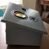
The drivers mounted - the final look

Dyn_Outdoor_20190601_093331.jpg
Photo: Another angle
 
I cut a space for the plate amp which will eventually be installed. But to test my design and to do measurements will experimenting on passive crossover designs, I made a blank panel with two speaker terminals to connect the speakers to amps.

Dyn_Outdoor_20190601_093337.jpg
Photo: Close up of temporary connection plate

Dyn_Outdoor_20190601_095734.jpg
Photo: Speaker mounted on stand and being measured to design crossovers and to verify the enclosure tuning.

Dyn_Outdoor_20190601_130503.jpg
Photo: Another angle of the speaker on a stand

Dyn_Outdoor_20190601_153927.jpg
Photo: The test rig... the pillows on the floor vastly reduce the floor reflection to I can get an accurate measurement down to approximately 700Hz which will outside of the crossover range where the drivers could be interacting.

Dyn_Outdoor_20190601_171352.jpg
Photo: You can see how I wired up the speakers. The plate was not 100% air-tight, so the bass response was not how it will perform in the final system.
 
Some more photos before I get into the crossover design process:

Dyn_Outdoor_20190602_122128.jpg
Photo: With all the practice, I have become pretty good at flush mounting drivers which improves the sound by vastly reducing edge diffraction from the driver's mounting flange.

Dyn_Outdoor_20190602_122132.jpg
Photo: Yet another view of the front and bottom of the speaker.

Dyn_Outdoor_20190602_140645.jpg
Photo: Here I am in the garage doing a set of quick on and off axis measurements to ensure my predictions were accurate and crossover design would result in a more usable end solution. I also experimented with a felt ring on the tweeter to see if it made an appreciable difference.

Dyn_Outdoor_20190602_140704.jpg
Photo: Another angle of the rush garage measurements. I ultimately chose not to use the felt ring on the tweeter.

Dyn_Outdoor_20190607_135054.jpg
Photo: Here are the frames for the grills. Since these are going to be outdoors for most of the year, I needed to protect them from bugs or other vermin - especially since there is a port and the acoustic damping material is a nice, soft, comfy cotton felt pad.
 
On crossover design....

When I design a passive crossover I like to start with a target goal for the final result. Naturally, a flat response and smooth off-axis performance is critical, but so is a smooth phase shift across frequencies and an easy amp load. I also want to use as few passive parts as possible since every part inherently detracts from the audible performance and fewer parts means lower costs per crossover allowing my to save money and/or use higher quality components which will sound better. I also design to a target SPL because different input voltages change the impedance characteristics of the drivers and thus impact the tuning of the passive crossovers. I know it is a mess, but this is why everyone isn't designing their own speakers.

First thing I like to do is get extremely accurate measurements of each of the drivers while installed in the enclosure so I am working with how the speakers will sound while installed. Many DIY builders measure drivers separate from the enclosures and as a result they get sorry crossovers and bad performance. Others rely on manufacturer's measurements or those made by "experts" on the web, which also results in poor crossovers and bad sound.

Next thing I do is use a DSP-based active crossover to experiment with potential crossover parameters and measure the resulting acoustic performance. Since I prefer simpler crossovers, I start with a simple 6dB Butterworth crossover filter in the digital processor and try to get good sound from the speakers. I then try out both Butterworth and Linkwitz-Riley 12dB crossover filters at various frequencies to see how good I can get them to sound and measure. Then I try 18dB versions, and so on. I have never gone to the trouble of building a crossover with more than 4-poles, or a 24dB slope, so I stop after working on 24dB slope digital crossover filters.

I then go over which of the dozen, or so, seemingly decent crossover settings I've tested and somewhat liked the results of and start whittling them down to just a couple so I can do some quick side by side listening tests of a few crossover configurations and determine which one sounds the absolute best. I then test the one that seems best on and off axis to determine if there are any extreme issues with the power response I need to worry about which might determine it unusable.

In the end, with these drivers in this physical configuration, I decided a simple 18dB per octave Butterworth crossover was the best sounding and measuring option which I felt I could build using passive filters.

So, with all the measurements from the speakers, knowledge of the crossover goals, and actual measurements of the drivers with the active filter in place, I went to my modeling software and started designing a passive circuit in the virtual world which replicates the performance of the active filters in the DSP, which are essentially ideal. It took a very long time and I struggled with the temperature fluctuations of the tweeter's voice coil between 0.5W versus 10W, but in the end I was happy with the results.

My only real concern with the finished design was a predicted dip in the impedance to about 3 ohms in the midrange. I ultimately decided that the amp we were using would easily handle that dip without too much trouble because the phase angle wasn't shifting insanely in the octaves around the dip and the digital amp IC is easily capable of handling 2 Ohms while generating 80W without any additional protection circuits. So, all things considered, I decided to go with this design despite the impedance hiccup.

The design completed, I had to order the components because I didn't have all the passive components I needed to even build a temporary test filter. So, I chose nice, somewhat reasonably price components and ordered what I needed.

When the parts arrived, I used a ton of alligator clip test leads to mock up a full crossover and measured the results on the actual speaker. I was going at it aggressively enough that I failed to take any photos of the rat's nest of wires and parts piled up on my breakfast table while I made measurements and listened intently. I did find that I had to slightly modify the inductor values for the woofer's crossover, which was easy enough since they needed to be a high value which meant simply unwinding the coil and measuring until I got the results I needed. Comparing the responses of the drivers with the passive mock-up crossovers to the measurements I took with the DSP filter in place, I was VERY impressed to see I was almost spot on across the operating range. YAY!

However, the real world impedance dip in the midrange turned out to have a minimum of 2.6 Ohms. Still safe with the amp we would be using, but if a passive input plate were going to be used with an external amp, this could present problems at high power levels for some amps - especially receivers or older amps. But, again, I chose to live with it.
 
Here are photos of my layout and assembly process for the passive crossovers:

Dyn_Outdoor_20190608_113258.jpg
Photo: Mounting the components on the boards. I use E6000 glue and zip-style cable ties to hold the parts in place. Note that the woofer crossover has the coils arranged so they are exactly perpendicular to one another, thus eliminating any mutual inductance where the signal passing through the coils is not captured and added to the signal in each other. This crosstalk is a significant cause of graininess and lack of resolution in lesser speaker systems and is relatively easily avoided by taking placement seriously.

Dyn_Outdoor_20190608_175238.jpg
Photo: here are all of the crossover boards. In order to allow for more mounting options, I separated the tweeter filter from the woofer filter. It also helps me separate the coil in the tweeter crossover from the two coils in the woofer crossover - again, to reduce or elimiate that crosstalk problem I mentioned above.

Dyn_Outdoor_20190608_175304.jpg
Photo: A close-up of the woofer filters - see how I took advantage of the inherent shape of the smaller coil to get the angle of its magnetic field exactly perpendicular to the other coil's magnetic poles?

Dyn_Outdoor_20190609_111013.jpg
Photo: Fully assembled with wires connected. I use simple, cheap #6 machine bolts and screws with eye-socket crimp on connectors to wire them up. Very effective, reliable, easily adjustable and still very affordable.
 
More photos:

Dyn_Outdoor_20190609_112015.jpg
Photo: To prevent any mechanical vibrations or rattling, I used some old cut-off neoprene foam discs from speaker seals I made for my top end statement speakers to mount the boards. I also placed the crossovers so the tweeter's coil is not only a good distance away from the woofer's coils, but it is still completely perpendicular to them. This should eliminate any possible mutual inductance between all of the coils resulting in higher resolution sound with less grain, grit, or low level distortion.

Dyn_Outdoor_20190609_112023.jpg
Photo: View of the crossover from above

Dyn_Outdoor_20190609_112029.jpg
Photo: Another view of the installed crossovers

Dyn_Outdoor_20190609_112350.jpg
Photo: A view of the inside after replacing the cotton acoustic insulation which covers the crossovers.

Dyn_Outdoor_20190609_112536.jpg
Photo: A view of the back of the baffle with the drivers connected.
 
And then the unthinkable!!! I had to make grills for these to protect them from insects and small animals. I used common window screen material as it won't mold or rot in the outdoor environment, and I like that I can see the drivers and port through it. The frame for the grill, as you can see above, has a 45 degree chamfer on the inside edge to reduce the affects of edge diffraction, but there will still be a audible effects than going without a grill. However, the offset drivers will help reduce the audibility somewhat by widely distributing the frequency and amplitude of the diffraction.

Dyn_Outdoor_20190609_160149.jpg
Photo: Speaker with grill place on it.

Dyn_Outdoor_20190609_160155.jpg
Photo: Speaker without grill

Dyn_Outdoor_20190610_091956.jpg
Photo: Both speakers with grills installed.
 
I mentioned earlier that the temporary input plate I was using was not airtight. Well, when I went to make final measurements it became apparent how much leakage there was. I could tell by the sound quality that it needed improvement, as it was loose, floppy, and a bit distorted in the bass.

When I went to measure the speaker, I was shocked at how much leakage there was, I could actually feel it on my hand when playing moderately loud music.

So, I took some time to make proper input plates which seal very well.

Dyn_Outdoor_20190610_094941.jpg
Photo: New input plates before gasket foam.

Dyn_Outdoor_20190610_163901.jpg
Photo: Neoprene dense foam gasket.

Dyn_Outlaw_20190610_163903.jpg
Photo: Closeup of foam
 
I then compared the difference in impedance between the old input plate and the final one:

Impedance_Plates_2019-06-12.png
Chart: Impedance of system with temp poor performing input plate (green) and with final high quality sealing input plate (blue)

That is a very dramatic difference! But what does that mean?

Here's the close mic measurements of the woofer and port using the different input plates:

InputCup_Good_vs_Bad.png
Chart: Close Mic acoustic measurements of woofer & port with temp poor performing input plate (black) and with final high quality sealing input plate (blue).

Notice that the efficiency of the woofer and port is significantly higher when I used the input plate which seals the enclosure much better.

Now, let's hope the amps seal the enclosure well!
 
I have been working on frequency response measurements to post and will provide those soon. I need to do some outdoor ground plane measurements, then I can produce the charts to post here.
 
I am the customer for these speakers and could not be more pleased or excited. These are going to look and sound fantastic on my back porch.
 
I failed to mention that while I had a rough idea of the requisite size and tuning of the enclosure based on manufacturer's specifications posted to the seller's website, before I actually designed anything I carefully measured the woofers after they arrived. After burn-in, they were very close to one another in measurements - a good thing. They were also within about 5% of the published specifications, making my estimations on the enclosure VERY close to the final design. Always a nice thing.
 
Back
Top