• Welcome to The Audio Annex! If you have any trouble logging in or signing up, please contact 'admin - at - theaudioannex.com'. Enjoy!
  • HTTPS (secure web browser connection) has been enabled - just add "https://" to the start of the URL in your address bar, e.g. "https://theaudioannex.com/forum/"
  • Congratulations! If you're seeing this notice, it means you're connected to the new server. Go ahead and post as usual, enjoy!
  • I've just upgraded the forum software to Xenforo 2.0. Please let me know if you have any problems with it. I'm still working on installing styles... coming soon.

The Anatomy of an LCD Projector

Batman

Well-Known Member
Staff member
Moderator
Famous
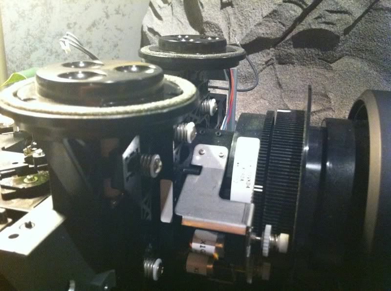
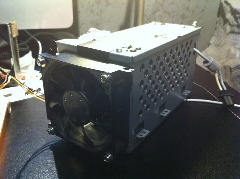
Thought you guys may enjoy checking out the innards of a Panasonic lcd projector. The model number is PT-AE1000U. I don't want to get into specifics of why or how it happened but long story short is that the cabinet was damaged during shipping and the projector was still fully functional (although it may not be when I'm through). The cabinet will be either replaced or repaired (if repaired, I know a guy). But either way it was really interesting getting down and dirty with this thing and how they are engineered.

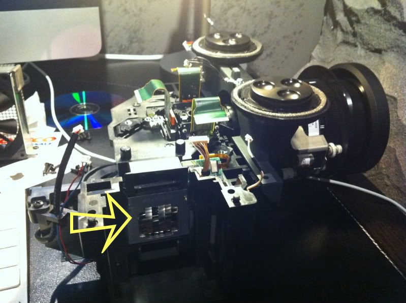
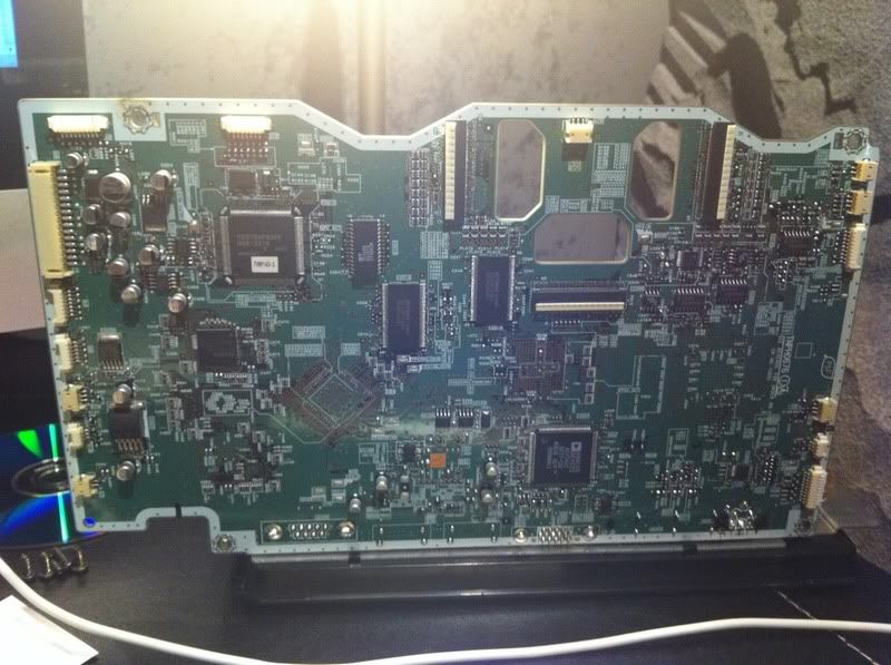
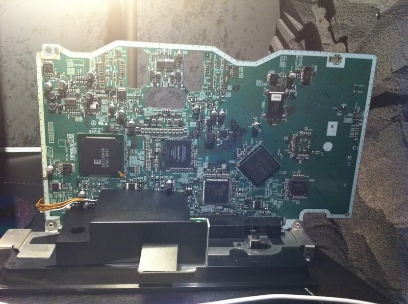
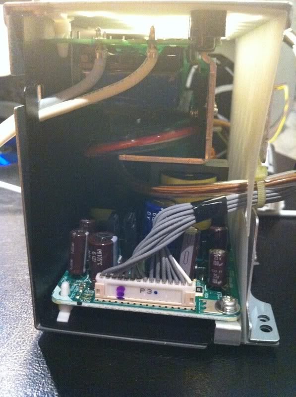
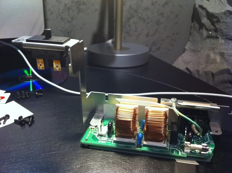
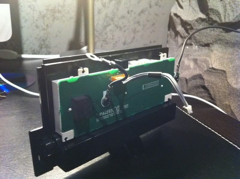
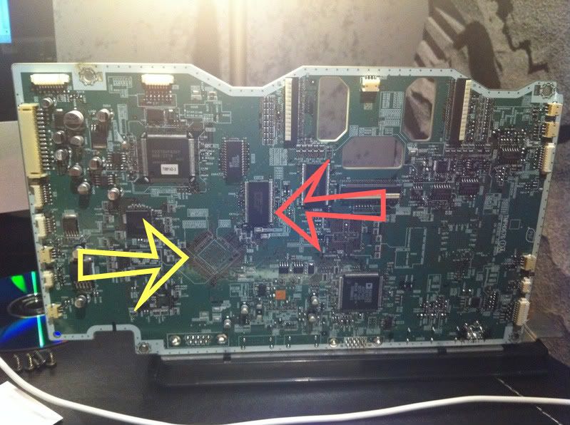
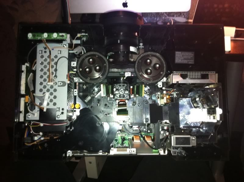
Top cover off, before tear-down, on second thought the main circuit board is removed from the unit in this pic...

3a8aa621.jpg


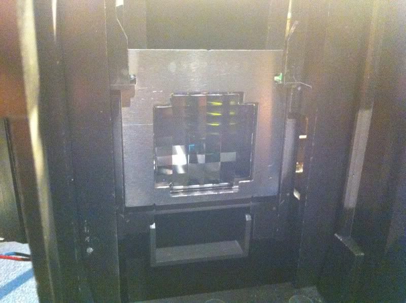
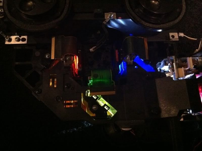
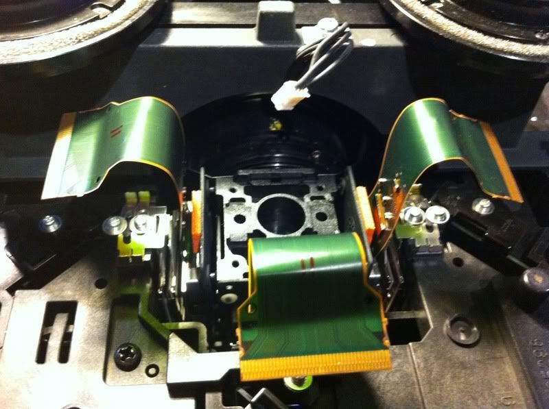
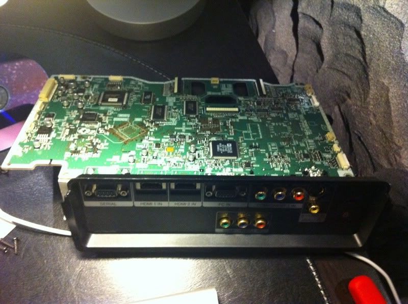
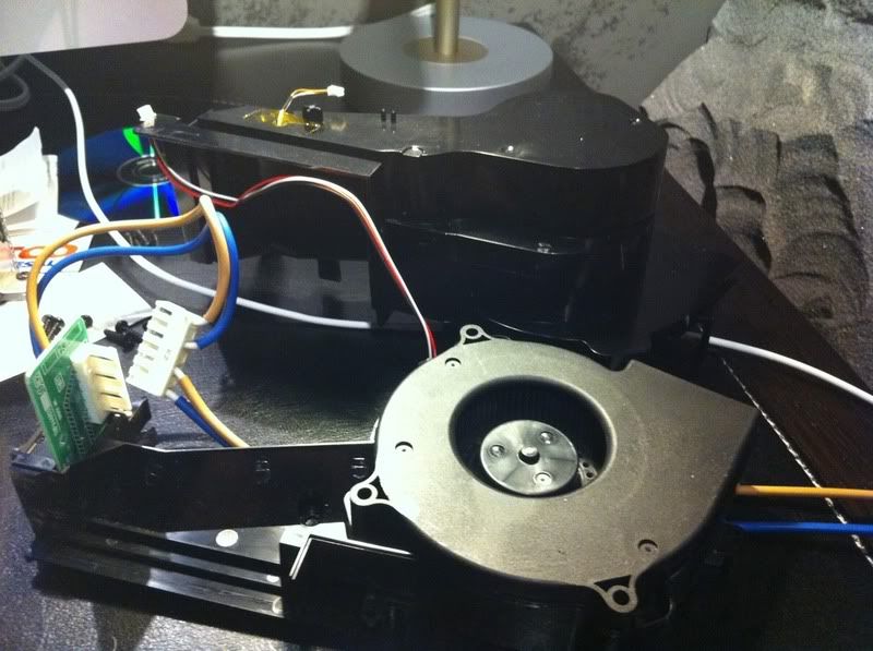
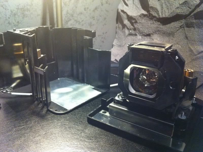
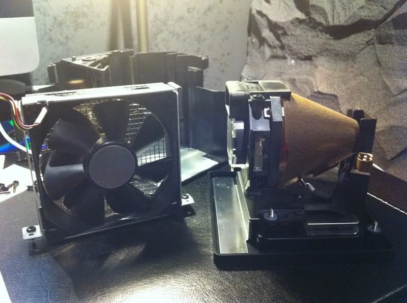
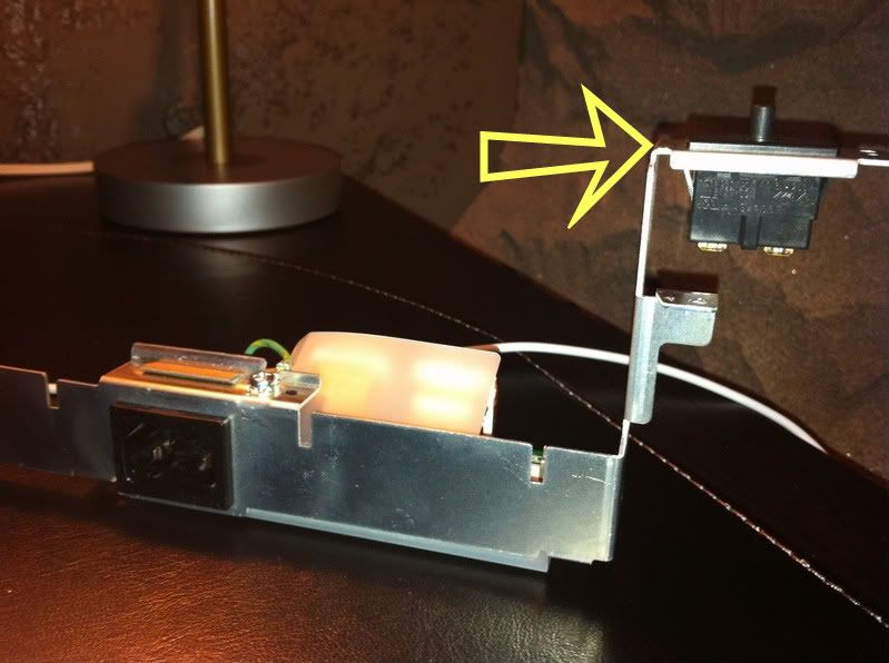
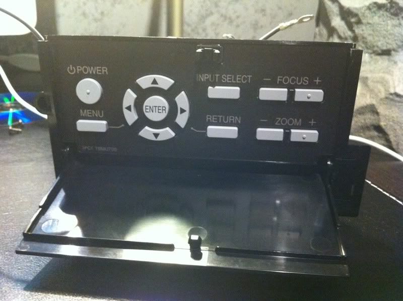
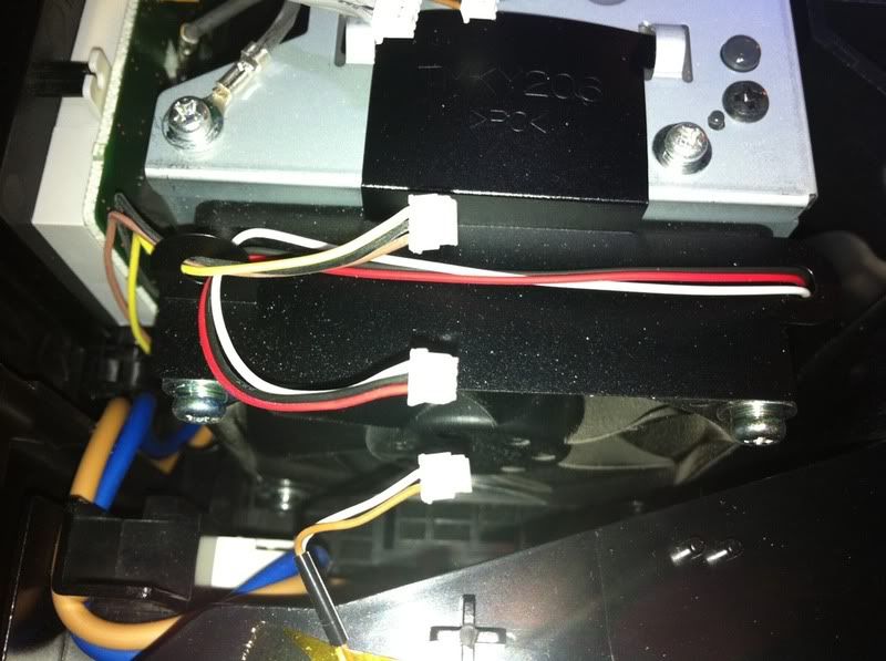
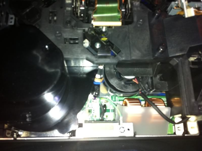
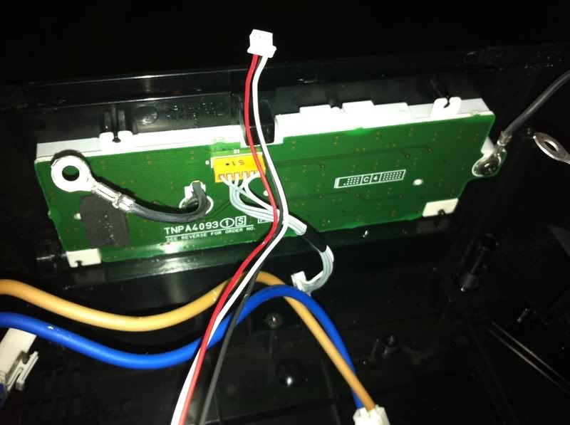
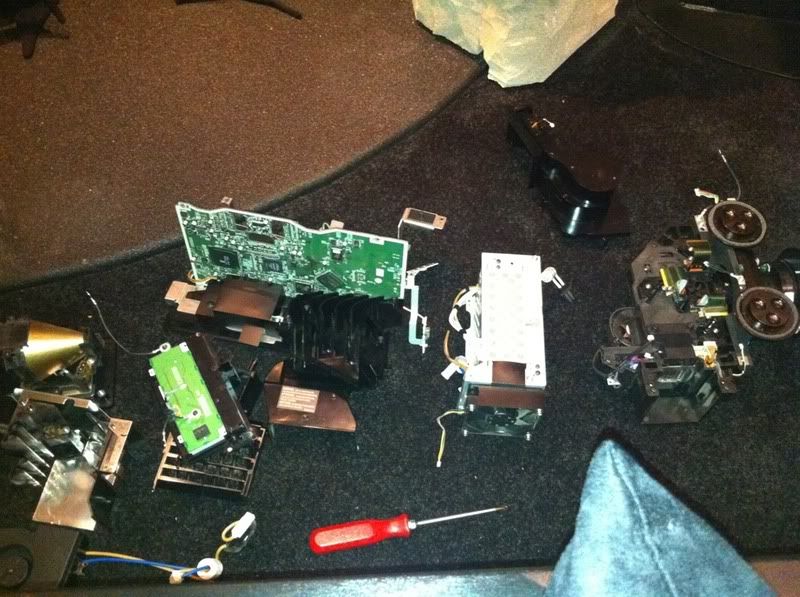
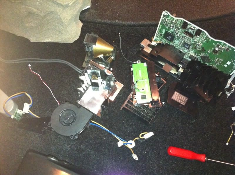
This is what I was left with after tear down...

f327b504.jpg


924a7d21.jpg
 
Now some of this stuff I recognize, other stuff I don't. I can make an educated guess based my limited knowledge so if someone knows something or I'm wrong by all means correct me. I thought this could be educational. We know that the AE1000 is a 3 LCD projector. This is a diagram of how a basic 3lcd projector works

0,1425,i=5265,00.gif


This is the lens, mirror, lcd, and projection lens assembly. I placed an arrow next the lens and it appears to have an actuator of some sort next to it. Perhaps to change the angle of the light coming through it. The bulb housing is aligned with it when assembled.

f6eb52cd.jpg


Lens close-up

59720e23.jpg


Here you can see how the 3 LCDs or the mirrors rather light up red, blue and green when light is shown through the lens...

f2b5c065.jpg


Here is the prism, the ribbons come up through the board (shown last post) and attach to electronic terminals.

983f4bae.jpg


Manual lens shift dials for vertical and horizontal shift and the gearing is for motorized zoom...

b0ad056f.jpg
 
Main circuit board. Obviously, there's all kinds of stuff attached to it. I noticed a Silicone Image chip near and lined up with the HDMI inputs and there is another chip that says Altera Cyclone. There are many others, but no identifying markings that I can decipher.

c1eea924.jpg


599e8cb4.jpg


2f37fd28.jpg


Power supply with attached cooling fan

42de7e86.jpg


Inside of power supply, I have no idea what I'm looking at here... :happy-smileygiantred:

9d0cc5e7.jpg


This is one of the few cooling fans in this unit, this one supplies filtered air to the lcd/prism assembly. The black cover is the top half and the two pieces combined form a duct.

f759aa8e.jpg


Lamp assembly and housing, and cooling fan for the lamp. The fan pulls the hot air across and away from the lamp and exhausts out the front of the projector.

05905078.jpg


e6908ef4.jpg


AC power socket, the arrow points out a spring-loaded switch that breaks the circuit if the lamp is removed...Second pic is the backside of the same piece

3d071dd1.jpg


28df513d.jpg


Operational buttons kind of speak for themselves and the second pic is the backside

9da7fac7.jpg


a0221857.jpg


That's pretty much it, I can't break any of these components down any further without risk of further damage or ruining the entire unit. So there you have it...
 
Just throwing this out there, but maybe this is a good time to do some sort of a custom cabinet.


You've already got the Batcave, I know you're thinking about some sort of 'bat projector' to add to the theme.
 
This is not the projector from my theater. This was a projector that I purchased for a video gaming area I am planning for the kids. It will go in a nook in the rec area of the basement. I will pair it with a 60" xscreen we received for free when B and I installed a Planar projector a couple years back...I am happy with the theater projector appearance, it's not really noticeable and when you look up it fits right in because of the way I hung it with exposed conduit and gas pipe fittings...However I appreciate the out-of-the-box line of thinking... :handgestures-thumbup:
 
Glad I took some pics in addition to those others to assist in reassembly... :eusa-whistle:

8121c48b.jpg


49b3a6d3.jpg


1e499edb.jpg
 
Now I want to tear down my JVC to compare the 3 chip LCD to the LCoS technology...but I'll resist the temptation... :happy-smileygiantred:
 
Any of you EE types explain why a circuit board would have just one large chip set at a 45-degree angle? There was plenty of room to mount it straight... :think:
 
Botch said:
Any of you EE types explain why a circuit board would have just one large chip set at a 45-degree angle? There was plenty of room to mount it straight... :think:
Botch, I think that because the way the chips align on either side that if the angled chip (yellow arrow) is aligned straight it would be up against the chip on the opposite side (red arrow). By spinning it 45 degrees, they can fit it where needed w/o touching. That's my guess and I'm sticking to it... :eusa-whistle:

c1eea924-1.jpg
 
I was actually looking at the pic just after the one you reposted; looked like there was enough room...
 
I explained my logic poorly I believe spinning the chip even though they're on opposite side leaves adequate room for the circuits themselves... Does that make more sense?
 
Just a wild guess... But it might have something to do with the location on the pins and their relationship to the various connection points on other chips or components. It might be that placing it at such an angle was required in order to avoid overlapping the routes between connections.
 
Towen7 said:
Just a wild guess... But it might have something to do with the location on the pins and their relationship to the various connection points on other chips or components. It might be that placing it at such an angle was required in order to avoid overlapping the routes between connections.
That much better articulates what I was trying to say. I did a horrible job of stating my explanation for it. But I'm in agreement... :text-bravo:
 
Batman said:
Towen7 said:
Just a wild guess... But it might have something to do with the location on the pins and their relationship to the various connection points on other chips or components. It might be that placing it at such an angle was required in order to avoid overlapping the routes between connections.
That much better articulates what I was trying to say. I did a horrible job of stating my explanation for it. But I'm in agreement... :text-bravo:
Ah, you both explained it. I didn't realize they were opposite sides of the same board... :facepalm:
 
Back
Top