• Welcome to The Audio Annex! If you have any trouble logging in or signing up, please contact 'admin - at - theaudioannex.com'. Enjoy!
  • HTTPS (secure web browser connection) has been enabled - just add "https://" to the start of the URL in your address bar, e.g. "https://theaudioannex.com/forum/"
  • Congratulations! If you're seeing this notice, it means you're connected to the new server. Go ahead and post as usual, enjoy!
  • I've just upgraded the forum software to Xenforo 2.0. Please let me know if you have any problems with it. I'm still working on installing styles... coming soon.

Flint Acoustics: Outdoor Coaxial System

While typing the previous post on these speakers I decided to show the impact of installation locations, mic placement, and such on the real listening experience on any set of speakers.

Here are two measurements showing how placement impacts performance:
Patio_Coax_18_ResponseAnechoicInstalled.jpg
Black Line: Response of installed right speaker from the most common listening position on my patio
Red Line: Response of same speaker in anechoic environment (9-1/2 ft above ground, over 23 ft from house or other hard surfaces)
I matched the output levels at 440Hz because that is the frequency I use to adjust for sensitivity calculations for 2.83V @ 1M.

It is clear that boundary reinforcement dramatically increased the output in the bass range by over 12dB of gain. Also, the treble is harsher due to the many hard reflective surfaces all around the speaker and the listener. I knew this would happen, hence my decision to design the cabinet loading on the woofer portion to have a weaker bass output in an anechoic space and cut the midrange as it would also boost.

Here's all of the measurements I took of both the left and right speaker from several spots on my patio: left seat, right seat, between seats, directly between the speakers, out in the yard, and standing on the front edge of my patio:
Patio_Coax_18_ResponseAllMeasurements.jpg
I also included the anechoic measurement and placed it's level based on the SPL at 1kHz being about average with the other curves. I set the levels of the other curves so they are almost all identical at 200Hz.

Notice the dip at 400Hz is almost the same from every measurement location and either speaker. However, it shifts from below 400Hz to above 400Hz based on the distance of the microphone from the reflective wall behind the seating. The widest about of variation in output is in the 500 - 800Hz range where either mic placement or using a different speaker created a variation of nearly 20dB SPL.

This just demonstrates how critical the acoustical environment in which you are installing speakers needs to be taken into account. You cannot look at a response chart on the web and assume that is how they well sound in your installation. However, you could look at the response charts of two speakers and get an understanding of how one might sound when compared to the other.
 
Making Progress on the commissioned versions of these speakers.

I made a judicious change in the baffle and cabinet for the coax to get away from perfectly square dimensions. The sub remains the same, though I chose a different bracing methodology to utilize a bunch of scrap MDF strips I have from other projects.

20190214_115410.jpg

20190215_141618.jpg


20190215_171828.jpg

I stopped working tonight by putting a liberal coat of a sealer on the outside panels of the subwoofer.
 
This morning I glued the rear panels on the satellite speaker cabinets, sanded and put another coat of sealer on the subwoofer, then started work on the sub's feet. For the feet are made from the disks of MDF left over when I cut out speaker, port, or input cup holes with my router. I glue two disks together to make 1.5" thick cylinder then sand the sides perfectly smooth, seal, then paint them. When I install them I use a rubber bumper, or foot, on the bottom. It looks good, uses some of my otherwise wasted material, and I can choose the color. On the original The Arthur subwoofer I painted them shiny gold and they look like metal. Not sure what I'll do on these.

ArthurSub_04.jpg
The sub cabinet is a perfect cube with strip bracing inside. When I tap the sides with my knuckle, each one has a slightly different pitch since the bracing strips are varying widths and placed randomly.

ArthurSub_05.jpg
The feet are MDF and after sanding them smooth, I dip them in the sealer to ensure they are non-porous before I paint them. This gets me a shiny finish on the end product.

LilJoker_02.jpg
This is a photo of both rear enclosures for the Lil Joker satellite speakers. Because they are small and identical, I can use one set of clamps to glue up both speakers simultaneously. Once these dry, I will quickly clean up the edges with a scraper and router. Then I'll sand them smooth before gluing the front baffles onto them.
 
Since the weather chose to be poor for painting from a spray can, I chose to spend today assembling the final crossovers for the Lil Joker satellite speakers and ensure my calculations result in performance as expected. I found that the filters works as designed, but the pad for the tweeter was way too little, so I experimented with different resistor levels until I got a great sounding and measuring tweeter level.

The future owner wanted the same performance they heard on my back patio, which had the low frequency boost from the proximity effect of placing them up in the corners under the "ceiling", so I had to alter the crossover filters to enhance the low end a bit - basically a baffle step compensation network. I also wanted to slightly reduce the treble from my original outdoor models since I listen at relatively low levels out there so as not to bother my neighbors - so I tuned the originals to have a bit of a loudness curve. The new owner will be primarily watching TV, playing games, and hosting parties where rap & hop-hop music will be playing. It is in an apartment, so levels won't be terribly loud, but the balance needs to be pretty good.


LilJoker_03.jpg
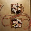
I use home-made alligator test leads to connect the components of the crossovers. That lone resistor at the bottom left serves as the pad for the system - this is a low budget way to reduce the voltage going to the tweeter and will increase the impedance above the crossover frequency by whatever value I use for that resistor. So, the 8 ohm load of the tweeter added to the 9 ohm load of the pad results in the speaker having an impedance of over 17 ohms in the tweeter's range. This has almost no impact on common solid state amps, but with a tube amp this would audibly alter the frequency response compared to a transistor amp.

LilJoker_04.jpg
The speaker cutouts are so perfect that I could press the speaker into the front and it held into place perfectly for these tests without using mounting screws. The cutout for the input cup, however, had wires hanging out of it, so I pressed the input cup over the hole and laid the other cabinet against it to hold it in place for the measurements. This resulted in a accurate measurements to under 400Hz, which is all I need for these crossovers. If I needed to get accurate measurements for lower frequencies, I'd have to find a way to properly seal the rear input cup hole.
 
Last edited:
No joke, someone on social media asked about the tape measure on the table near the speaker enclosure. I sarcastically said it was important to consider the length of the wires I was using and compensate for them in my measurements. I wasn't thinking and thought it was funny.

It has started a shit war, and I am shocked people are defending my facetious response.
 
Ha! People are arguing that wire length will audibly impact time alignment and even levels!!!

Has anyone mentioned that electricity moves through copper wire at roughly three million meters per second?
 
Has anyone mentioned that electricity moves through copper wire at roughly three million meters per second?
This may in fact be true, but still your ignorance on the matter is very real. Everyone knows you can double that speed and increase the consistancy in which the electrons flow by placing a AA battery in line with said wire.
 
Has anyone mentioned that electricity moves through copper wire at roughly three million meters per second?

Stop it!!!

You are not allowed to bring things like facts, science, and empirical data of any sort into discussions like this.
 
Subwoofer has been assembled and tested. I am running it for a few hours to make sure nothing starts rattling. It is a little strange listening to my auditioning playlist through only a subwoofer which operates, though rolled off, to about 300Hz.

ArthurSub_06.jpg

ArthurSub_07.jpg

ArthurSub_08.jpg
 
Here's my initial measurements with the subwoofer sat upright (driver firing down) and the measurement microphone placed on the floor just inside the edge of the cabinet. At my seated location about 1.5M away and about 1M from the floor the SPL at 60Hz was 87.5dB.

BassDecay_Sub.png
The "Bass Decay" measurement in the OmniMic software is designed to represent how bass rings in a listening room, but in this case I used it to look for resonances in the subwoofer. An absolutely ideal curve would be smooth from a high at 20Hz to the low at 200Hz. In this case it isn't perfectly smooth with what looks like a resonance at about 37Hz and a null at about 43Hz. However, those anomolies are very minor and I can happy to live with them as I don't think they will be audible in real world listening. Chances are good they are caused by the vibrations of the cabinet walls - the most common cause of losses in the enclosure when it is completely sealed such as this one.


CSD_Sub.png
I turned off all gated in the OmniMic software and measured the cumulative spectral decay of the woofer with the close mic setup. In this case it is very tight. The main system resonance is at 60Hz as I calculated it would be based on the T/S parameters of the driver and the volume of the enclosure and losses (vibrations and added internal dampening). THis is a very typical response for small sealed subwoofers. I will make a similar measurement of my SVS SB12 NSD to compare sometime.


THD_Sub.png
The THD is also pretty good with the typical increase in 3rd order below the primary resonance of the system (60Hz). That added 3rd harmonic will actually give the impression more depth is coming from this subwoofer below 50Hz. Note, this is the response with close mic placement and not a typical in room response. I will measure that later and post it.
 
And here is a decent in room response of THE ARTHUR subwoofer.

Sub_BehindSeat.png

I'd say this is a pretty decent sub.
 
Just finished assembling the passive crossovers for the Lil Joker satellites. I debated adding a tweeter level switch, but to save a few bucks I chose not to. Everything is glued onto the board and I used nylon zip ties to hold everything in place even if the glue fails. These will be screwed into the inside of the rear wall on the cabinet. I am most likely to solder the leads to the terminals on the speaker and input cup. But, I have plenty of quick connectors if I choose to go that route.

LilJoker_05.jpg
 
Fully assembled and I just ran a QC test to ensure they were operating as expected. So far I am getting almost exactly what I expected.

Here's a quick measurement of the frequency response of one Lil Joker with The Arthur subwoofer in a mid-sized bedroom, sub in the corner.

LilJoker+TheArthur_InitialResponse_InRoom_2019-02-22 (2).jpg

I tuned it for a significant dip in the midrange and a boosted very top end. This gives it that common sizzle you hear at most mainstream retail stores. The bass with the subwoofer is solid to under 40Hz and is very smooth. Other than the acoustics based dip at about 210Hz, the frequency response is within +/-2dB from 46Hz to 1,400Hz. This is pretty darn good, overall.

I will do proper speaker measurements later, but for now I am enjoying the sound.
 
Integral to this system is the use of a 2.1 amplifier. In this case I am using the Dayton Audio DTA2.1 digital amplifier which can generate up to 50 watts per stereo channel and 100 watts for the subwoofer output.

https://www.parts-express.com/dayto...ifier-with-sub-frequency-adjustment--300-3831

It has all the expected features, but of interest for this project is the tone control, which works as a high frequency damper. Since these speakers are tuned to be bright, the owner can use the tone control to get a less bright sound if desired.

I decided it would be interesting to see the range of filter on the top end by measuring the speaker with the control to max and them to minimum:

DaytonAudio_BT2.1Amp Tone Control Range.png

The tone control cuts the treble at 10kHz by as much as 14dB. At 4kHz it cuts by as much as 11dB and at 1kHz as much as 3dB. It impacts the frequency at frequencies as low as 200Hz, which is pretty interesting.

I chose a setting above the middle point which has the most natural brightness and marked it on the knob/faceplate as a reference for the owner.
 
The customer picked up the speakers today. He was VERY pleased with the sound, the functionality of the amplifier, the look, and the modularity of the system. I am glad he liked them. He is intending to attach the analog output form this TV into one of the analog inputs on the amp and then use his phone via Bluetooth to play music.

I hope they work well for him for years to come.
 
Back
Top