
You are using an out of date browser. It may not display this or other websites correctly.
You should upgrade or use an alternative browser.
You should upgrade or use an alternative browser.
How to build amp measurement gear?
- Thread starter PaulyT
- Start date
 - mainly I need to order the load resistor(s).
soundhound, with 8 Ohm dummy load already in place, putting a 10k ohm potentiometer in parallel (lets say half way turned so that it creates 5K Ohm resistance), wouldn't that drastically change the total capacitance of dummy load?soundhound said:Then you need a 10k ohm potentiometer of any wattage. Wire the input terminal of the pot to a 100k ohm resistor (any wattage), and then the resistor to the hot side of the load resistor and the ground side of the pot to the ground side of the load resistor. Then take the middle (wiper) terminal to the input of your soundcard. This gives you 20dB of voltage attenuation on top of the range of the pot. You adjust the output of the pot to a reference level on your test program (it should be as high as possible but not clipping the input of your sound card).
soundhound
Well-Known Member
DIYer said:soundhound, with 8 Ohm dummy load already in place, putting a 10k ohm potentiometer in parallel (lets say half way turned so that it creates 5K Ohm resistance), wouldn't that drastically change the total capacitance of dummy load?soundhound said:Then you need a 10k ohm potentiometer of any wattage. Wire the input terminal of the pot to a 100k ohm resistor (any wattage), and then the resistor to the hot side of the load resistor and the ground side of the pot to the ground side of the load resistor. Then take the middle (wiper) terminal to the input of your soundcard. This gives you 20dB of voltage attenuation on top of the range of the pot. You adjust the output of the pot to a reference level on your test program (it should be as high as possible but not clipping the input of your sound card).
You weren't paying attention in class. There is a 100k resistor in series with the input of the pot.
:doh:
Ok, but "ground side of the pot to the ground side of the load resistor" will still make it a loop thus parallel connection (w/ more impedance). I'm just wondering if it will create slightly lower than 8 Ohm dummy load or it's so little that it's negligible. :confusion-scratchheadblue:
Ok, but "ground side of the pot to the ground side of the load resistor" will still make it a loop thus parallel connection (w/ more impedance). I'm just wondering if it will create slightly lower than 8 Ohm dummy load or it's so little that it's negligible. :confusion-scratchheadblue:
Couple more questions, soundhound.soundhound said:You can test amplifiers up to 100 watts output with this arrangement.
1. What occasions would someone need to use that many watts when measuring amp's sound characteristics? I can see someone needing that much for testing the clipping limit of amp but just wondering.
2. For measuring amp at average listening level, would 20 - 30 watts dummy load be sufficient?
Update:
8 Ohm 100w resistor arrived yesterday so I assembled a dummy load with a trim pot.

Hooked it up and did a bit of testing. It does show some results but the test had to be a very short one due to smell of smoke. It was coming from my ss amp. Immediately, I shut it off and unplugged everything. Later I checked the amp for its performance (sound) and it still works. Whew! :shock:
I'm thinking that the resistor in the middle is too high even though it's 20K Ohm. I had to turn the amp's input gain and the trim pot on the right all the way up to get some voltage at the RCA plug which may have caused something in the amp to overheat. Couple weeks ago, I've measured my ss amp without dummy load while only using that trim pot to adjust for >1 V at the amp's output and the whole session went without a problem. Could the culprit be turning the amp's input level all the way up?
8 Ohm 100w resistor arrived yesterday so I assembled a dummy load with a trim pot.
Hooked it up and did a bit of testing. It does show some results but the test had to be a very short one due to smell of smoke. It was coming from my ss amp.
Immediately, I shut it off and unplugged everything. Later I checked the amp for its performance (sound) and it still works. Whew! :shock: I'm thinking that the resistor in the middle is too high even though it's 20K Ohm. I had to turn the amp's input gain and the trim pot on the right all the way up to get some voltage at the RCA plug which may have caused something in the amp to overheat. Couple weeks ago, I've measured my ss amp without dummy load while only using that trim pot to adjust for >1 V at the amp's output and the whole session went without a problem. Could the culprit be turning the amp's input level all the way up?
soundhound
Well-Known Member
From the photo, you have everything wired correctly. I would stick with the value of resistor you have now. The load should not (cannot) cause the amp to smoke if its truly an 8 ohm resistor, and you don't have the speaker load connected to the amp output too. Something else is wrong. The amp level control would have nothing to do with the load resistor setup.
soundhound
Well-Known Member
A 100W load resistor should get warm to the touch when it is dissipating around 25 W or so, and should only get really hot when its getting toward 75-100 watts if it is not attached to a heatsink. My guess is that you amplifier is oscillating at some frequency (assuming you're not feeding a signal to it). Why that should happen I can't diagnose without being there, but there is something very wrong, and I don't think your load resistor is at fault.
soundhound
Well-Known Member
IMD, noise floor, phase linearity. That's about all that you can do with that program. Frequency response is better measured by TrueRTA.DIYer said:I just downloaded free 21 day trial version of Multi-Instrument Pro. Besides harmonics measure, what are other telling parameters of amp I should measure?
I've been looking at the samples of amp measurements online and one thing I notice that's in consistent, why is frequency response measured at 1W output while harmonics and IMD are measured at much higher output? Link Shouldn't they all be measured at the same condition the amp is put under? :confusion-scratchheadblue:
soundhound
Well-Known Member
Transistor amps have trouble in some cases at the highest audio frequencies where they can't deliver full output. Testing at 1 watt presents a level playing field.
Here are my first attempt at using Multi-Instrument Pro after calibrating. For objectivity sake, I will withhold the name of the amp I tested until later.
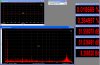
This is harmonics and a few other parameters at 20W 8 Ohm output. I'm not sure what that peak at 17KHz is. :confusion-shrug:
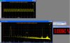
These are IMD measurements at 20W 8 Ohm output.
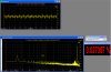
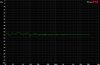
Here is 1/24 octave frequency response at around 45W 8 Ohm output measured with RTA.
This is harmonics and a few other parameters at 20W 8 Ohm output. I'm not sure what that peak at 17KHz is. :confusion-shrug:
These are IMD measurements at 20W 8 Ohm output.
Here is 1/24 octave frequency response at around 45W 8 Ohm output measured with RTA.
Attachments
soundhound
Well-Known Member
You should use the linear graph mode rather than the log representation as this lines up the harmonics on divisions which are easier to intrepret.
soundhound
Well-Known Member
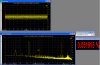
DIYer said:How about this? I'm still not sure what's causing those two peaks at 15.9KHz and 19KHz. They are not there when I measure direct "out" to "in" of sound card so it must be the amp.
Hard to tell what the cluster of noise (or oscillation) is in the 15-17kHz range. The amp under test seems to be a differential design, with quite a lot of global negative feedback.
BTW, use the dBr setting on they "Y" axis as this automatically places the test tone at 0dB (full scale) which expands the range below it, and allows easy reading of the levels of the harmonics and noise.
soundhound
Well-Known Member
The amp appears to be very noisy which is obscuring the distortion spectra. You might also try lowering the resolution of the FFT: try 8024 or 4096, and set to "Hanning" for the FFT type.