soundhound
Well-Known Member
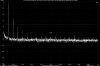
DIYer said:Does it have something to do with bias voltage? I have it set at 1.1VDC instead of standard 1.56VDC. I've read it somewhere that the original design was made when typical residential wall outlet was supplying around 115VAC 40 years or so ago.soundhound said:I think the high noise floor of your interface is obscuring most of the view of the distortion products. The Dynaco MkIV is a bit surprising because the sidebands on the sides of each distortion product is intermodulation distortion (IM).
The only thing that having the bias lower than usual would do is to make the amp clip at a lower wattage than otherwise. The bias voltage reading is independent of the AC line voltage (which was 117 VAC in the 1950s-60s rather than 120 VAC today). I think there's something else going on because those distortion sidebands are not normal operation.